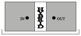
Notch Filter 210 VHF cavity
The Notch Filter is used when high attenuation is required for narrow spacing between the working and the rejected frequency. Attenuation and Insertion Loss can be adjusted by the rotating loops of the cavity. It is used for frequency spacing of 300 KHz. or less. It is installed in a single base frame 5 units 19″ cabinet.
Electrical Specifications
| Frequency band: | 118 – 144 MHz |
|---|---|
| Impedance: | 50 Ω |
| Max Power: | 200W CW |
| Insertion loss: | Adjustable 0.5 dB ÷ 2.5 dB |
Mechanical Specifications
| Connector Type: | N Female |
|---|---|
| Dimension: | 19” rack, 5HU, depth 684 mm. |
| Operating Temp.: | -10°C to +55°C |
| Tuning method: | Rotary knob, telescopic movement |
| Notch Filters | Channels | Cabinet 5HU | Frequency Spacing (KHz.) | Attenuation (dB) |
|---|---|---|---|---|
| MCP210-V/2 TI | 1 | 1 | 50 | ≥ 25 |
| 100 | ≥ 30 | |||
| 200 | ≥ 40 | |||
| 300 | ≥ 40 |
last update 27 June 2017


