Band Reject Filter 210 VHF cavity
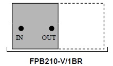
One or two Band Reject Fillters can be allocated in one 5 unit 19” cabinet. Frequency tuning and rejection can be regulated through adjustable mechanical knobs.
Electrical Specifications
| Frequency band: | 118 – 144 MHz |
|---|---|
| Impedance: | 50 Ω |
| Max Power: | 100W CW |
| Insertion loss: | ≤ 1.5 dB |
Mechanical Specifications
| Connector Type: | N Female |
|---|---|
| Dimension: | 19” rack, 5HU, depth 728 mm. |
| Operating Temp.: | -10°C to +55°C |
| Tuning method: | Rotary knob, telescopic movement |
| Band Reject Filters | Channels | Cabinet 5HU | Attenuation (each single cavity) |
|---|---|---|---|
| FPB210-V/1BR | 1 | 1 | ≥ 22 dB, @ +200KHz or –200KHz notch ≥ 40 dB, @ +500KHz or –500KHz notch |
| FPB210-V/1-1BR | 2 | 1 | ≥ 22 dB, @ +200KHz or –200KHz notch ≥ 40 dB, @ +500KHz or –500KHz notch |
last update 27 June 2017


